 Digital Handstand

UI interactions
How the 3D view, sketch tools, constraints, dimensions, and body tools work together.
FlywheelCAD is built as a hybrid tool: fast direct manipulation in the UI, backed by a script editor that stays synchronized with the model. This page focuses on how to operate the visible interface efficiently.
Window Layout
| Top toolbar | Contains view switching, drawing tools, trim and construction mode, extrude/revolve, constraints, dimensions, the variables panel, plus the Sketches and Bodies menus. |
| Main canvas | Shows either the 3D scene or the active 2D sketch plane. You switch between them as you model. |
| Right panel | The live Python script editor. It shows the current model as text and has stop/run controls for replaying the script. |
3D View
Enter sketch mode
Double-click a sketch plane in the 3D view to edit it. The app also lets you switch to
any existing sketch from the Sketches menu in the toolbar.
Select bodies and topology
In 3D mode you can select bodies, areas, and topology points. Those selections feed the
Bodies menu, section/project commands, and custom sketch-plane creation.
Custom sketch planes
Select exactly three 3D points, then use Sketches → Create Sketch from
Points. The app asks for a plane name and emits a matching
create_sketch_plane(...) command into the script.
Body operations
The Bodies menu handles boolean union, difference, and intersection,
plus section, project, loft, and 3MF export. Mesh quality can also be changed there.
Per-body color and finish are set from Bodies → Set Color….
Components, Libraries, and Assemblies
Insert from Library
Component → Insert from Library… opens a movable browser of the
installed libraries (the built-in standard library of motors, servos, bearings,
fasteners, extrusion, and linkage — plus any of your own under
~/Documents/FlywheelCAD/Libraries/). Pick a part, adjust its parameters
with a live 3D preview, and insert. The module is copied into the document’s
lib/ folder and the import + factory + instance lines are appended to the
script. Update from Library refreshes vendored parts when their source
library changes.
Place and mate instances
Component → Browse / Place Components… places instances of the
components defined in the document. Select an instance anchor and another point in the
3D view, then Component → Mate Points snaps them together — the
same closed-form mate you can write as cad.mate_coincident(...).
Author and insert your own
Component → New Component… starts a standalone component file;
Export Selected Body… and Export Selected Point as
Anchor… promote a body or point while editing one. To place a loose
component .py that isn’t in a library, use
Insert Component from File… — it copies the file in and adds the
instance.
Project files
A document is a flat .py or a .fwcad project
bundle — a folder that keeps the script and everything it imports together.
The File menu converts between them (Convert to Project
Bundle… / Export as Flat Script…), copies a helper in
with Add File to Project…, and reveals a bundle’s insides with
Show Project Contents.
Sketch Mode
Once you enter a sketch plane, the canvas switches to 2D editing. The active sketch name is shown at the top-left of the canvas, and the toolbar changes from scene-focused actions to sketch-focused actions.
| Select / pan / zoom | Use selection mode to pick geometry or closed areas. Pan and zoom tools are available explicitly in the toolbar, and the select tool also supports drag-based selection and point dragging. |
| Draw tools | FlywheelCAD provides line, circle, arc, ellipse, rectangle, and spline tools. Some tools have submodes: circles cycle through center-radius, diameter, and three-point; ellipses cycle through two-foci and three-point; rectangles cycle through corner and center-based creation. |
| Construction mode | Toggle construction mode when you want guide geometry that remains visible but is dashed and excluded from area detection for body creation. |
| Trim and mirror | Trim edits elements in place and can split them into reusable fragments. Mirror works on the selected elements, using the last selected line as the symmetry line. |
How Drawing Works
1. Choose a tool
Pick line, circle, ellipse, rectangle, spline, arc, or trim from the toolbar. Re-click a multi-mode tool to cycle through its submodes.
2. Place geometry directly in the sketch
Draw by clicking in the canvas. During creation the app shows preview geometry, then commits the final points and curves to the active sketch plane.
3. Edit by selection or drag
Click entities to select them. Drag a point in select mode to move it while the solver tries to keep the sketch consistent with existing constraints.
4. Select areas for bodies
Click inside a closed loop in select mode to select a detected region. Those selected areas become the input to extrude and revolve.
Constraints and Dimensions
Geometric constraints
In select mode, pick the relevant points, lines, circles, ellipses, or splines, then open the chain-link menu. The menu only enables constraints that fit the current selection, such as horizontal, parallel, concentric, equal, tangent, or symmetry.
Dimensions
Use the ruler menu for point distance, point-line distance, parallel distance, line length, circle or arc radius, and line angle. Each dimension can be bound to a constant, an existing variable, or a new variable created on the spot. Dimensions draw in standard CAD style — extension lines and double-headed arrows parallel to the measured span, leader lines for radii, and arc annotations for angles — in a distinct teal so they never read as sketch geometry.
Variables panel
The variables panel is where you inspect named dimension variables, rename them, and keep shared values consistent across multiple dimensions in the same model.
Solver feedback
After a constraint or dimension is added, the sketch re-solves asynchronously so the UI stays responsive instead of freezing during convergence work. A status badge reports whether the sketch is under-, fully-, or over-constrained — including how many degrees of freedom remain — and, when constraints conflict, names the ones the solver cannot satisfy.
From Sketches to 3D Bodies
When you have one or more closed selected areas, use the extrude/revolve tool in the toolbar. The app opens a small panel for operation type, distance, direction, or revolve angle. After the operation completes, return to 3D view to inspect the result and combine it with booleans or other downstream features. Bodies stay tied to the sketch they came from — edit that geometry and they re-derive — and selecting a body in the 3D view lets you delete it, which cascades to any boolean or offset bodies built on top of it.
# Typical sketch-to-body progression
cad.with_sketch("xy")
...
plate_region = cad.region(loop=[la1, la2, la3, la4], holes=[[hole]], inside=(-50, 0))
plate = cad.extrude("xy", plate_region, 10)Esc cancels the current drawing operation or
returns to 3D when idle. L, C, E, R,
A, and T switch tools. X toggles construction mode.
Enter finishes a spline.
Example Gallery
These screenshots come from the bundled example scripts and show the kinds of UI outcomes described above: body creation, multi-plane work, and boolean modeling.
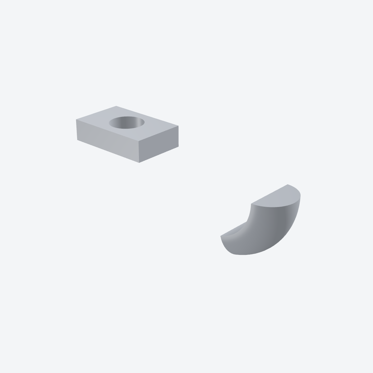
test_extrude_revolve.py
A typical sketch-to-body workflow: closed regions selected in sketch mode, then turned into an extrude and a revolve.
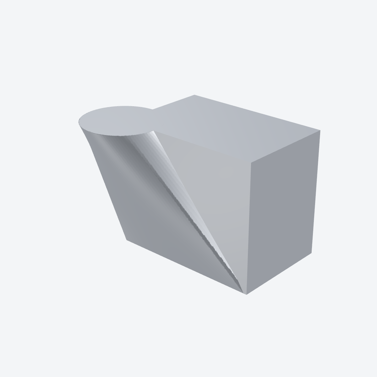
test_loft.py
Shows the handoff from a sketch on one plane to a custom-plane feature and a lofted result in 3D view.
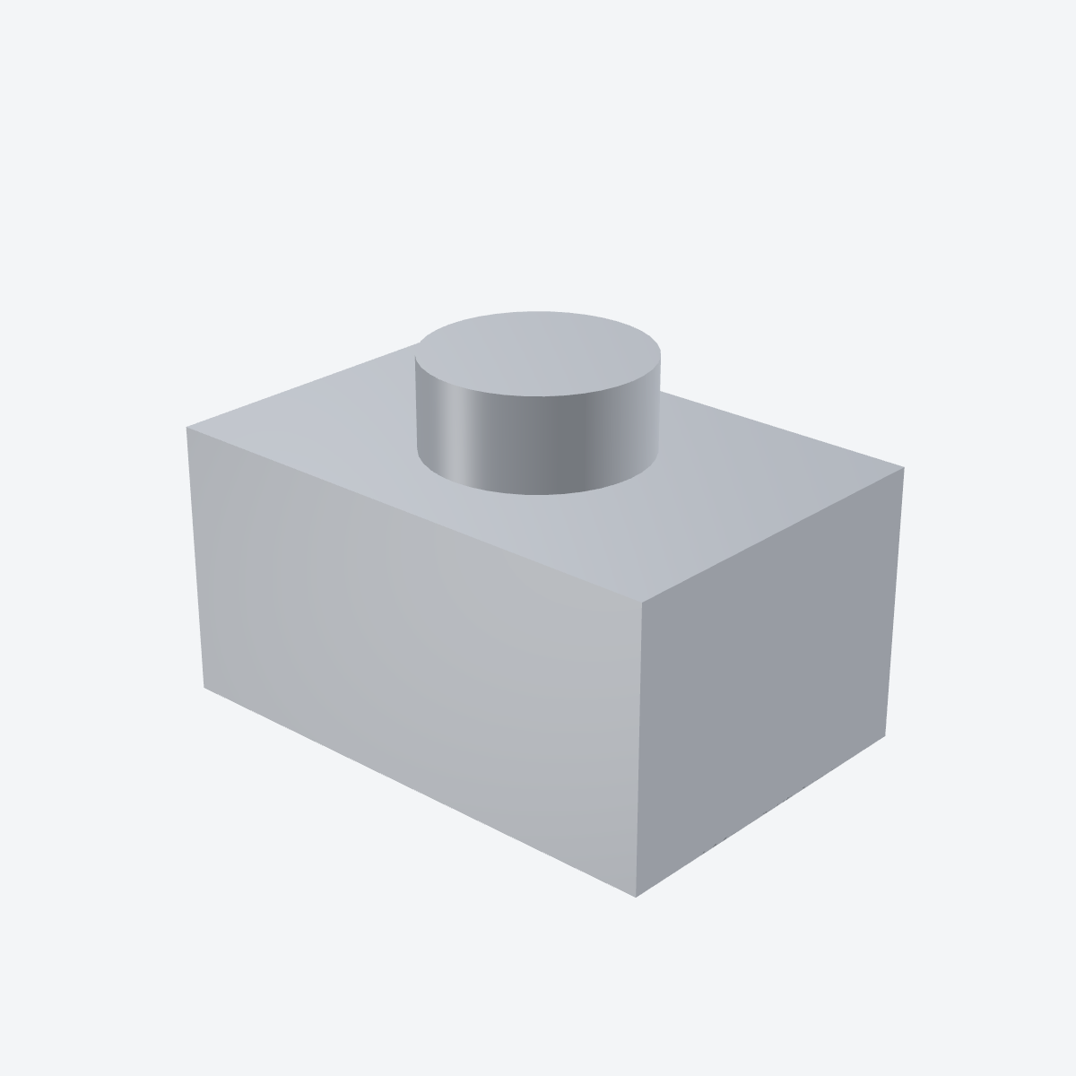
test_boolean.py
A straightforward subtractive modeling flow after creating the source bodies from sketches.
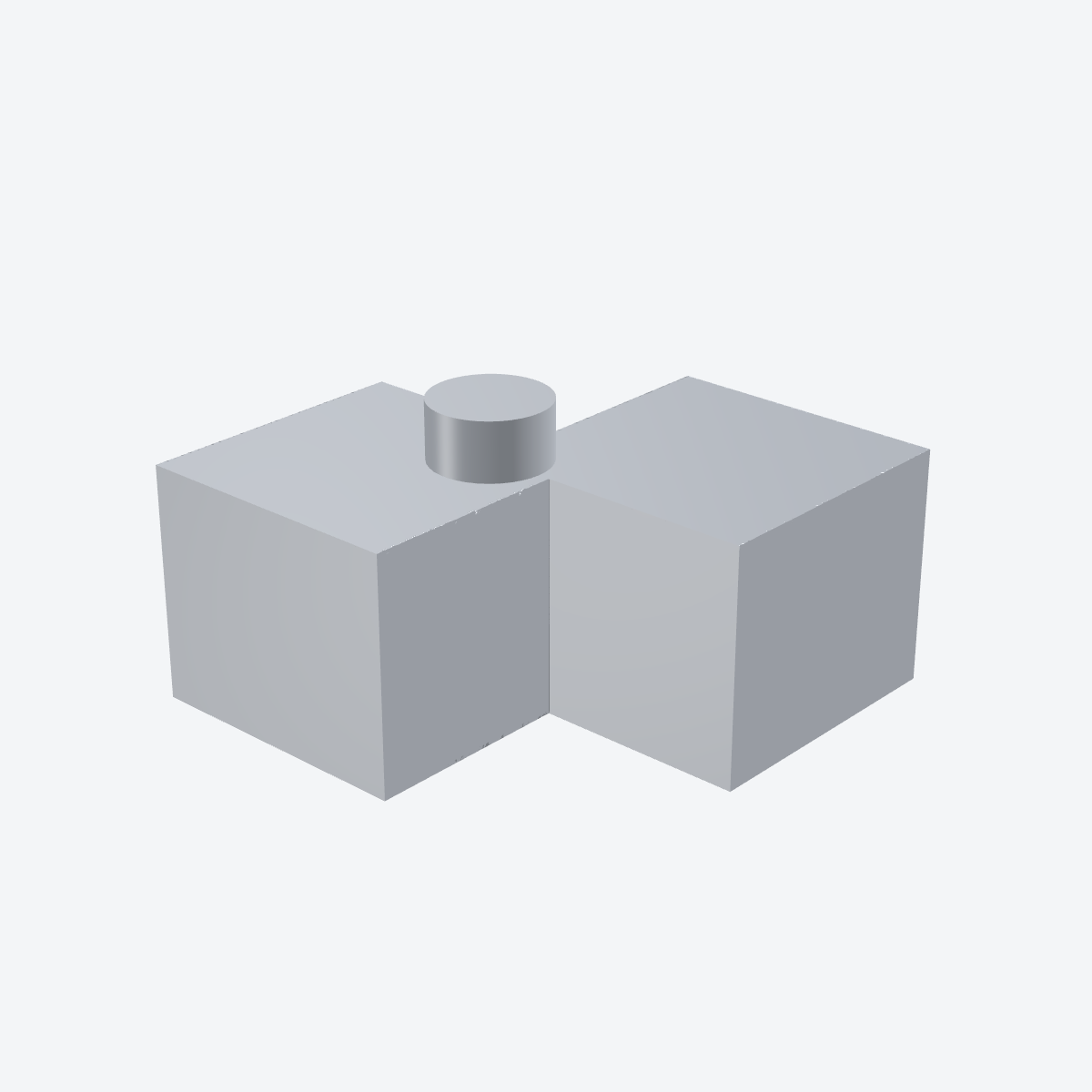
test_boolean_ops.py
Overlapping bodies selected and combined through union, intersection, and subtraction in the Bodies menu.
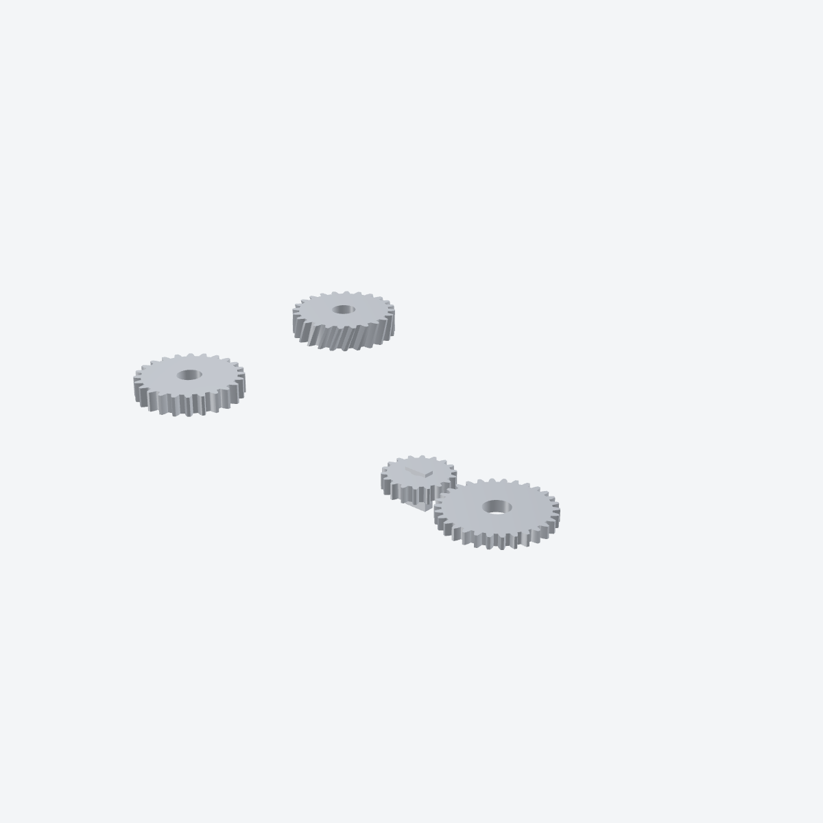
test_gears.py
Imported helper code generating dense sketch geometry that still ends up as normal, inspectable bodies in the same UI.