 Digital Handstand
FlywheelCAD
Python-first, constraint-driven CAD for reproducible sketch and body workflows.
FlywheelCAD combines direct sketch editing in the UI with a live Python script backend.
You can draw and constrain geometry interactively, create bodies with extrude, revolve,
loft, and booleans, compose reusable components into mated assemblies, export bodies as
.3mf files for 3D printing, then edit or rerun the generated script as the
repeatable source of truth.
The beta is signed but not notarized, so macOS will warn on first launch. If “Open” isn’t offered directly, open System Settings → Privacy & Security and click Open Anyway next to the FlywheelCAD entry.
What You Can Do
Sketch and constrain
Create points, lines, circles, arcs, ellipses, splines, and trimmed geometry, then solve sketches with geometric constraints, dimensions, and shared variables. A live status badge tells you whether a sketch is under-, fully-, or over-constrained, and which constraints conflict.
Build bodies and analyze them
Turn closed regions into solids with extrude, revolve, and loft — with optional
edge rounding, wall taper (draft), plane-normal offset, and twist for helical and
herringbone shapes. Then use boolean union, subtraction, and intersection (with optional
smooth or chamfer blends at the seam), derive sections and projections from bodies, and
export finished geometry as .3mf for 3D printing. Bodies are parametric:
edit the sketch they came from and they re-derive, and they can be deleted, cascading
to anything built on top of them. Meshing runs on the GPU — including whole
boolean trees evaluated in a single pass — and when a preset isn’t fine
enough for a small detail, set_cell_size pins an absolute mesh resolution
per body.
Work across multiple planes
Sketch on the standard xy, yz, and zx planes,
then define custom sketch planes directly from topology points of existing bodies.
Multi-section lofts sweep one smooth solid through any number of cross-section
planes — the sample aircraft fuselages and wings are built this way.
Compose components into assemblies
Define a part once inside with cad.component(...), export its bodies and
named anchor points, then place it many times with cad.instance(...) —
translated, mirrored, scaled, or rotated — and snap instances together with mates.
Components can be parametric (one wing factory, many wings), live in their own files
next to the assembly, and nest into sub-assemblies that re-export parts of their
children. Per-body colors and finishes (matte, glossy, metallic, glass) carry into
.3mf export.
Place parts from component libraries
Catalog parts come from component libraries — folders of
parametric part modules. A standard library ships in the app (NEMA stepper motors,
hobby servos and control horns, metric cap screws / nuts / washers, deep-groove ball
bearings, T-slot extrusion, and RC linkage hardware); add your own as folders under
~/Documents/FlywheelCAD/Libraries/. Component → Insert from
Library… browses them with a live 3D preview and parameter fields.
Inserting is copy-on-use: the module is vendored into the
document’s lib/ folder, so a design stays self-contained and a later
library update never silently changes it — Update from Library refreshes
vendored parts on your terms.
Keep everything reproducible
The right panel keeps the model as editable Python. A document is a plain
.py file or a .fwcad project bundle — a
folder that packages the script with everything it imports, so it moves and shares as a
single self-contained item. Helper modules live next to the main file (or drop one in
with File → Add File to Project…, or place a loose component with
Component → Insert Component from File…). Writing scripts with an AI
assistant? Drop the
AI scripting guide
into its context — it is the full API reference in one machine-friendly Markdown file.
Sample Assemblies
Five complete multi-file assemblies show the component workflow end to end: components defined in their own files, parametric part factories, instances placed with mirrors and transforms, mates snapping everything to named anchor points, and catalog parts pulled from the standard component library. They are the best reference for structuring a real project — download them with the Sample Assemblies bundle and open the top-level file as the document. (Assembly geometry lives inside the component files, so these show the composed 3D result; click to enlarge.)

Glider/glider.py
A sailplane with a multi-loft fuselage (rounded nose cap, cockpit, tail boom), a parametric NACA-profile wing with non-linear taper, washout, and dihedral — instanced once per side with the left wing mirrored — and a symmetric-airfoil T-tail, all placed on a common frame with per-component colors.

ToyAirplane/airplane.py
The introductory assembly: fuselage, parametric wing (instanced right and mirrored left), and tail, each defined in its own component file and mated to named mount points exported by the fuselage — move a mount and the parts follow.

AirplaneNested/airplane.py
A two-level assembly demonstrating nesting: leaf parts (fuselage, wing, engine, stabilizer) compose into sub-assemblies (a powered wing, an empennage) that re-export parts and anchors of their children, and the top assembly places and mates the sub-assemblies as opaque units.
FlyingWing/flying_wing.py
A tailless flying wing in the spirit of the Prandtl-D research aircraft: a NACA 4412 center section swept and tapered outward with the bell-spanload twist schedule (the tips fly at negative incidence), a pusher motor pod with spinner and prop, and elevons cut from the wing as separate bodies — a V-groove hinge opens downward from the upper skin, with an embedded servo, control horn, and pushrod on each side. Geometry-heavy generated-from-math modeling throughout.
MotorMount/motor_mount.py
A standard-library showcase: a mounting plate whose every cutout is a declared region
hole, populated with catalog parts placed straight from the component library — a
NEMA 17 stepper, a servo with a control horn mated onto its output spline, four
M3 cap screws, and a 608 bearing pressed into its seat, each in its own display color.
Its vendored lib/standard/ travels with the sample, so it opens and builds
self-contained.
Showcase Projects
Five short, heavily-commented projects teach the FlywheelCAD workflow one concept at a
time — sketching with constraints, body creation, lofting, components, and the
standard library. Read the comments top to bottom; they are meant to be learned from, not
just run. Download them with the
Showcase Projects bundle and
open each folder's .py file as the document.
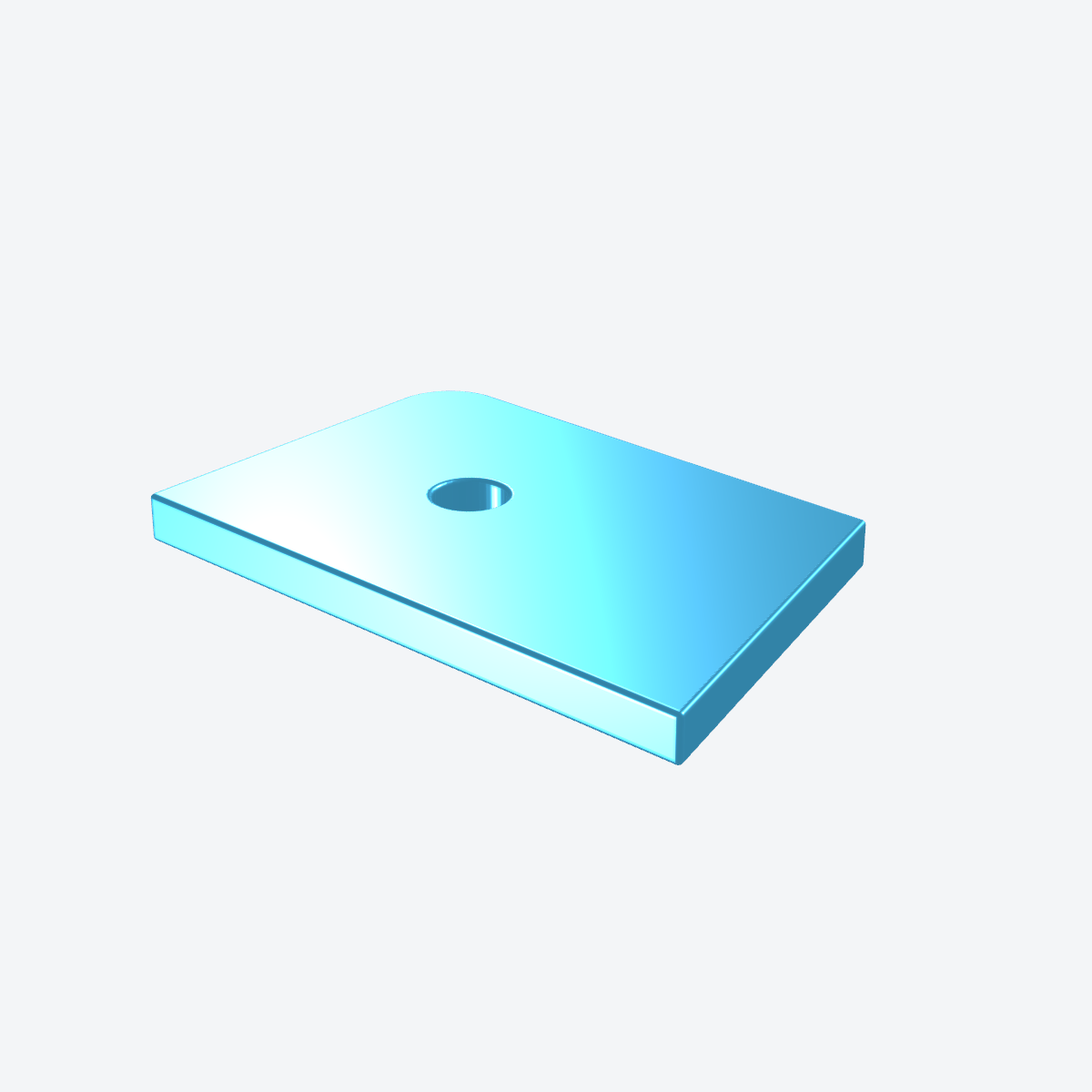
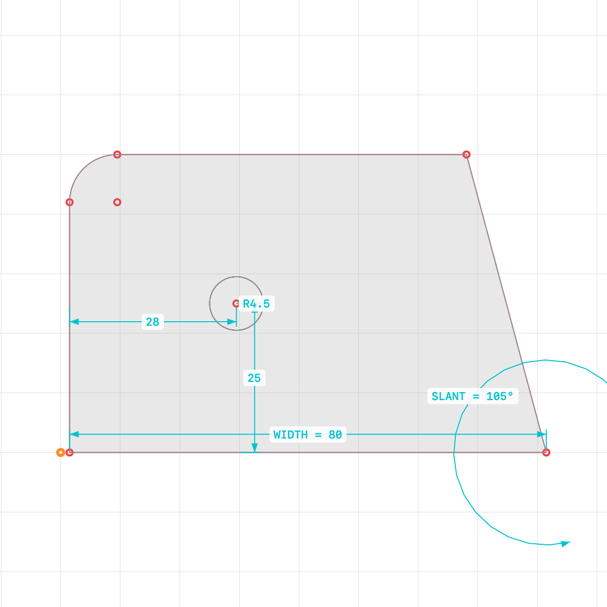
1 · Sketching, constraints & dimensions — 01_sketch_bracket/bracket.py
A flat mounting bracket drawn as a rough sketch, then pinned with geometric constraints
(horizontal / vertical / parallel / perpendicular and a tangent fillet) and dimensions
bound to shared variables. Change WIDTH, HEIGHT,
HOLE_DIA or SLANT and the whole part re-solves; a light
extrude lets the profile read in 3D.

2 · Body creation: extrude + revolve + booleans — 02_knob/knob.py
A machine hand-knob built from both body operations: a revolved, dished body, an
extruded central boss unioned on, a ring of extruded cylinders unioned then
differenced to scallop the rim into finger grips, and a subtracted shaft bore
— along the way showing edge_radius, offset, and boolean
union / difference.

3 · Custom planes & multi-level loft — 03_loft_duct/duct.py
A transition fairing that morphs from a nearly-round inlet to a wide, flat outlet.
Custom sketch planes stacked along the axis each carry a reusable oval cross-section (a
shared profiles.oval(...) helper), and cad.multi_loft(...)
sweeps one smooth solid through all four sections with no internal seams.

4 · Components: fixed + parametric — 04_standoff_kit/standoffs.py
A base plate with four hex standoffs, contrasting the two ways to define reusable parts: a fixed component that builds one specific part and exports named anchor points, and a parametric factory that makes any size on demand and is memoised per size. Instances are placed by mating their base anchor onto the plate's exported anchors.

5 · Library insertion & mating — 05_bearing_block/bearing_block.py
A pillow-style bearing block with a 608 ball bearing pressed into its bore and four cap
screws holding it down — catalog parts (bearing, cap_screw)
pulled straight from the standard component library and mated onto the block's anchors.
Its vendored lib/standard/ travels with the sample, so it opens
self-contained.
Script Quick Start
A FlywheelCAD file is ordinary Python. The minimal pattern is to import the API, create a
FlywheelCAD object, enter a sketch context, then emit geometry and body
operations.
from flywheelcad import *
cad = FlywheelCAD()

cad.with_sketch("xy")
p1 = cad.point2d(-60, -12.5)
p2 = cad.point2d(-20, -12.5)
line = cad.line2d(p1, p2)
cad.horizontal(line)
cad.length(line, 40)
When you need reusable logic, keep helper files next to the main script and import them directly. The included gear examples use exactly that pattern.
from flywheelcad import *
from CADgears import gear_outline

cad = FlywheelCAD()
gear = gear_outline(center_x=0, center_y=0, tooth_count=24, module=5.0, plane_name="xy")
body = cad.extrude("xy", gear["region_ring"], 24, quality="high")Bring Your Own AI
FlywheelCAD contains no AI integration — no cloud connection, no account, nothing leaves your machine. It doesn’t need one: because every document is ordinary Python, any coding agent you already use can write and refactor your models for you.
That is what the AI Scripting Guide is for. It packs the whole scripting surface — the rules an agent must follow, the full command reference, and worked patterns — into one Markdown file sized for an assistant’s context window. Drop it into a session with the coding agent of your choice, describe the part you want, and let the agent work out the hard geometry: circular-arc approximations of involute gear teeth, accurate NACA airfoil sections, parametric part families driven by a handful of variables. The meshing gear pairs in the test projects and the NACA-profile glider wing in the samples are exactly this kind of generated-from-math geometry — ordinary Python logic emitting FlywheelCAD commands.
Whatever the agent writes stays a plain .py file: open it in the app, run
it, inspect the result, and keep editing by hand or by prompt — the script remains
the single, reproducible source of truth either way.